V-Lab @ ANDC

First Order Low-Pass Filter Using Operation-Amplifier.

Aim

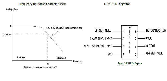
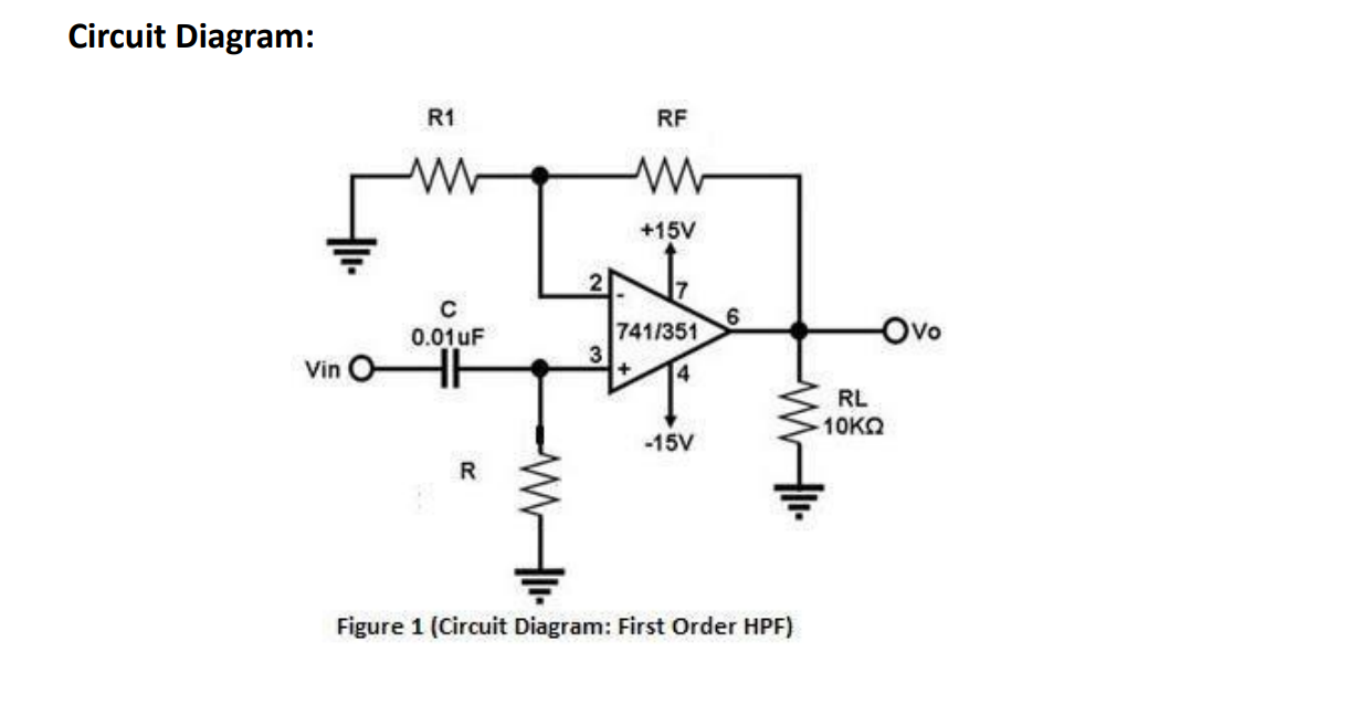
Desiging of a first order low-pass filter using op-amp (IC 741) .
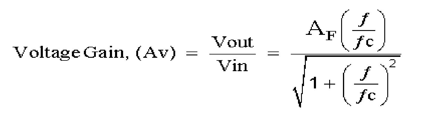
Apparatus

  1. Breadboard
  2. Resistance(1/4 watt)
  3. Ceramic capacitor
  4. 3 CRO Probes
  5. CRO (Cathods Ray Oscilloscope).
  6. Function Generator and Constant Power Supply

Theory

  1. In figure1.represent the Circuit diagram of first-order Butterworth low-pass filter
  2. In a low-pass filter,frequencies greater than a cut-off frequency f0are block
  3. figure1 represent the-investing ampilfies.Configuration,with anRC Circuit present at the non- investing input for filtering of the signal with the high-frequency.
  4. the cut-off frequrncy fcof the above Circuit can be determined by the Value of Rand C i.e,
    fc=1/2pie RC
  5. Gain of a first order low pass filter is given by the expression below:
  6. Where
    AF = the pass band gain of the filter, AF = (1 + RF / R1)
    ƒ = the frequency of the input signal in Hertz, (Hz)
    ƒc = the cut-off frequency in Hertz, (Hz)

  7. Practical Frequency Response characteristics of First order low pass filter is as below :

Procedure

  1. fine-tune the Cathode ray osilloscope being used for theis experiment for the measurment of amplitude and frequency .
  2. then generate a sinusoidal waveform signal with Vi=VP-P amplitude and 10Hz.frequency using the function generator.
  3. Connect the discrete component having values calculate above as perour desigining filter on the breadboard >
  4. Connect the input terminal VI with the Function Generator and Connect C.R.O at the Output terminals pf the op-Amp(IC-741)
  5. Now,fix the input Voltage Vi 1VP-P and vary the input frequency (f) from 10Hz to 100Hzand note down the corresponding value of output Voltage (V0)
  6. Calcuate the Gain of the low pass filter using the formula as given below:
    Gain=V0/Vi
  7. After this Calculate the Corresponding values of the gain magnitude in dB which is approximately equal to 20logV0/i
  8. Plot the frequency response graph of First order LPF between frequency and Voltage gain (the graph should be similar to the graph represent in figure 2) .
  9. After plotting the graph,Calcuate the cutt-off frequency fCand roll off factor of the First Order filter and then Compare the theoretical Values with the practical Values .

Animation

Question

  1. Give some examples of electronic circuits where high pass filter is used?
  2. Does a differentiator act as a high pass filter? If yes, explain how
  3. Derive the formula of cut-off frequency fc = 1/{2π(RC)} for a first order active Butterworth high pass filter.
  4. What is Gain Bandwidth Product of an amplifier?
  5. What do you mean by cut off frequency (fc) of a filter?
  6. What is the difference between the Butterworth & Chebyshev & Cauer filter?
  7. What do you mean by order of a filter?